
Here is an overview of Edge Computing realized by 5G. It is officially defined under the name MEC (Multi-Access Edge Computing). MEC has been standardized by 3GPP, the European Telecommunications Standards Institute (ETSI).
With the introduction of 5GC (5G Core), MEC will be available. MEC is one element to realize ultra-low latency of 5G.
- Benefits of MEC (Multi-Access Edge Computing)
- MEC server location and latency
- UPF (User Plane Function) and MEC server deployment scenario (physical installation location)
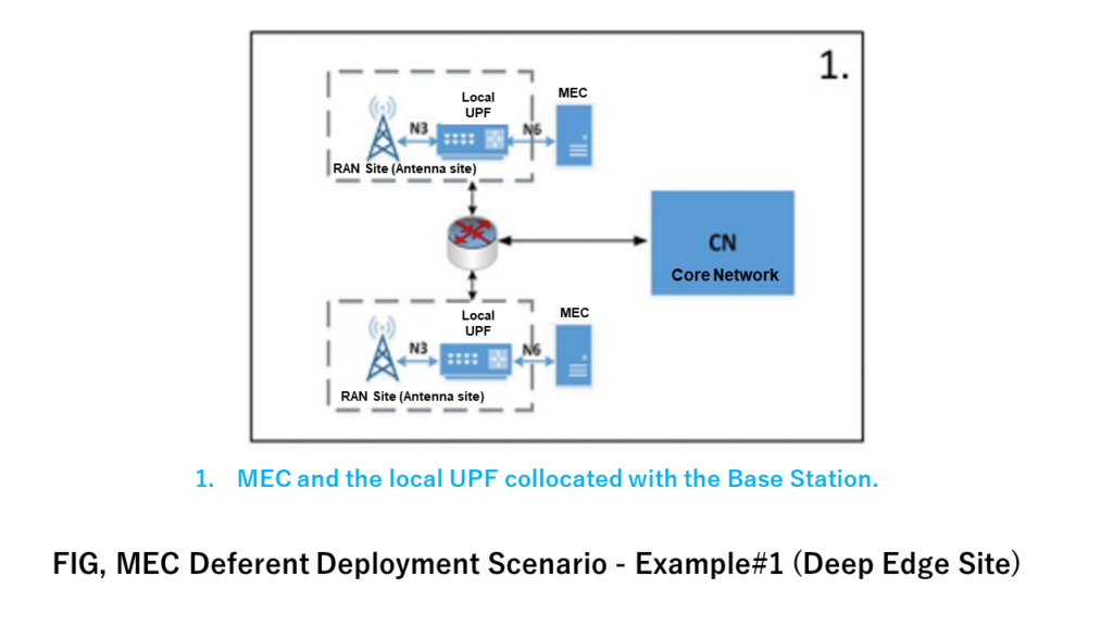
- Base Station (RAN antenna site) and MEC server are installed together [Deep Edge Site]
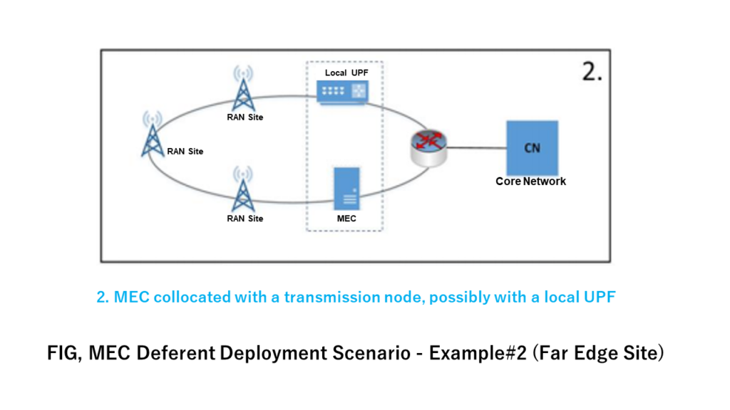
- RAN transmission node and MEC server are installed side by side [Far Edge Site]
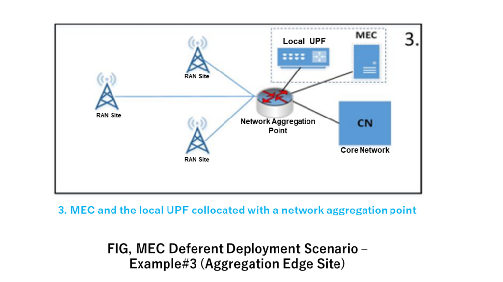
- Network aggregation point and MEC server are installed side by side [Edge Site]
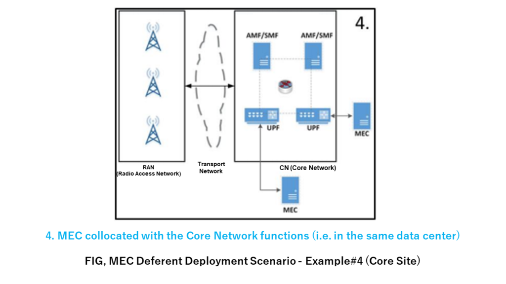
- Core network and MEC server (side by side in the same data center) [Core Site]
- MEC key technology
- Summary
Benefits of MEC (Multi-Access Edge Computing)
The advantages of Edge Computing (MEC: Multi-access Edge Computing) are the following two points.
(1) Network traffic is reduced
(2) Communication latency is reduced
The figure below shows the advantages of these two points. MEC is a simple technology with the concept of bringing an application server closer to the user.
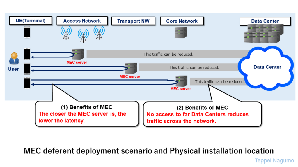
In 4G Networks, application servers and could are often located in large data centers. MEC (Multi-access Edge Computing) installs an application server that provides services near the user. This also known as Edge Computing. After the 5G Network is upgraded to SA (Stand Alone), MEC will be available.
MEC server location and latency
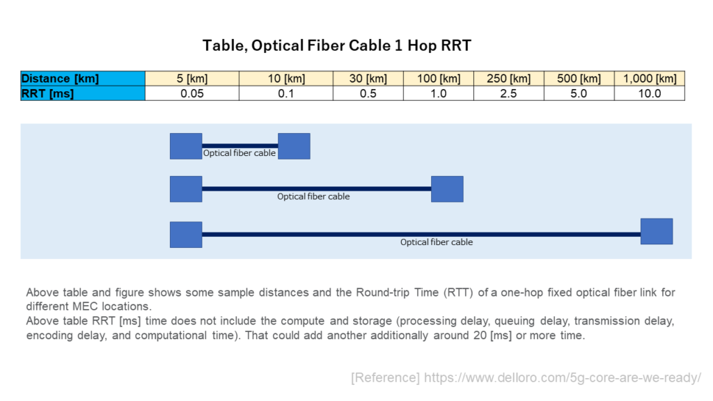
Optical Fiber Cable 1 hop Latency in MEC
On the network, the longer the distance of the transmission line from the terminal (smartphone), the longer the latency time. The figure below summarizes the relationship between the distance to the access destination server and the latency time. The relationship between the optical fiber 1 hop RTT [ms] and the distance was organized below.
User Level Latency in MEC
In an actual network, processing time, encoding time, processing wait time, etc. occur on many devices in the network. The figure below shows the relationship between the physical distance and the approximate latency (communication delay time). It shows the latency [ms] according to the distance to the MEC server.
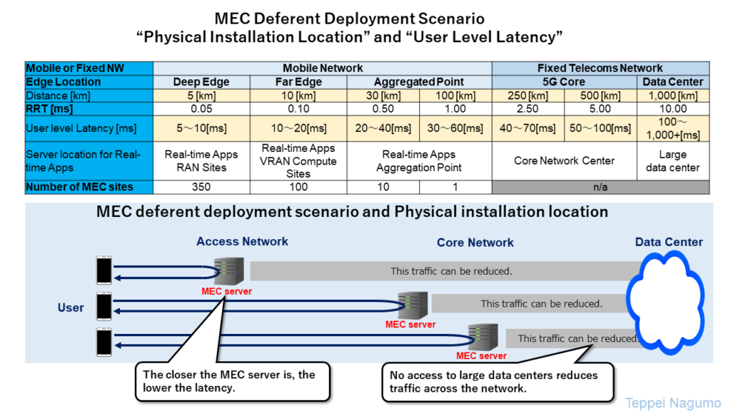
Latency is very long when edge computing (MEC) is not used. When MEC (Multi-Access Edge Computing) is used, the latency will be shortened. At the same time, the traffic of the entire network will be reduced by MEC. Because we don’t have to access a distant server or data center in MEC case.
UPF (User Plane Function) and MEC server deployment scenario (physical installation location)
The MEC server handles User-Plane (user data) for 5G traffic. The Control-Plane of 5G traffic is not handled by MEC. The UPF installed with the MEC server near the user is called the Local UFP (Local User Plane Function).
In 5G Network, UPF and MEC servers are standardized by 3GPP so that they can be installed quite freely. When accessing the MEC server, User Data goes through the Local-UPF between the MEC server and the User terminal. It is referenced from the White Paper on 5G MEC of the European Telecommunications Standards Institute (ETSI).
MEC in 5G networks, ETSI, White Paper [PDF file]
The following describes different deployment scenarios for MEC. The table below summarizes the relationship between MEC deployment scenarios (4 examples) and User Level Latency.
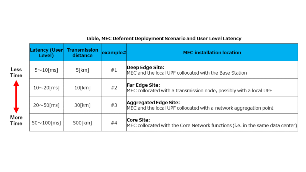
Base Station (RAN antenna site) and MEC server are installed together [Deep Edge Site]
This is a case where the MEC server and Local UPF are installed near the RAN antenna site and DU.
RAN transmission node and MEC server are installed side by side [Far Edge Site]
This is a case where MEC and local UPF are installed on the fixed transmission line (Mid-haul or back-haul) in RAN.
Network aggregation point and MEC server are installed side by side [Edge Site]
Case where MEC and local UPF are installed at the aggregation point of the RAN base station (antenna site or DU aggregation point).
Core network and MEC server (side by side in the same data center) [Core Site]
Case where UPF (it is not local UPF) and MEC are installed in the station where Core Network is installed.
MEC key technology
MEC System Architecture Overview
The figure below shows how MEC connects to 5G Network. The distributed MEC server is connected to the 5G Core UPF. It is referenced from ETSI white paper.
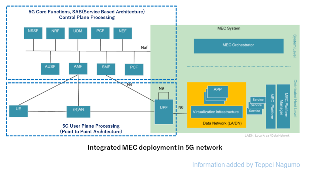
For more information on 5G Core networks, please refer to the following blog post.

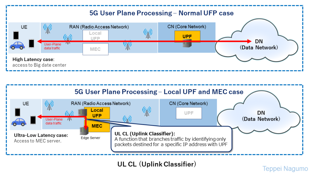
Uplink Classifier (UL CL)
In 5G networks, user data (U-Plane) is usually connected to the Internet or data center via UPF. UP CL (Uplink Classifier) is a technology that switches the forwarding destination to the MEC server only when using MEC. With the UP CL function, UE will be connected to the MEC via the Local UPF only when using the MEC.
MEC is expected to be used in services that achieve low latency. The figure below shows a normal processing case in 5G and a case using Local UPF and MEC (Ultra-Low Latency use case).
Session and Service Continuity (SSC)
MEC is designed to switch MEC servers when the terminal moves. It is necessary to switch the edge server used when the terminal moves. If the device moves, a new connection will be established. At the same time, technology is adopted that makes it possible to retain the connections that were previously held.
Session and Service Continuity (SSC) is a technology for smoothly switching the connectivity of mobile terminals. SSC of 5G Network prepares the connectivity of mobile terminals as three modes according to the requirements of the application.
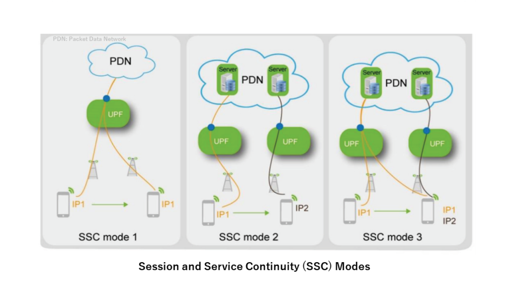
- SSC Mode1: Even if the UE moves, it follows the same route (same UPF) on the network. The UE continues to use the same IP address.
- SSC Mode2: When the UE moves, disconnect the connection that UE had until then and reconnect at the destination. The IP Address changes depending on the movement, and there is a non-communication timing due to switching.
- SSC Mode3: When the UE moves, establish a connection at the destination. At the same time, it retains the connections it had so far. Two IP addresses, an existing one and a new one, are assigned. There is no non-communication timing.
Summary
We have summarized the outline of Edge Computing MEC (Multi-Access Edge Computing) realized by 5G.
The advantages of Edge Computing (MEC: Multi-access Edge Computing) are (1) network traffic is reduced, and (2) communication latency is reduced. MEC will be used in the process of 5G sophistication. It is expected that new services will be realized with low latency.
For the overall technology of 5G, please refer to the following blog post.


コメント